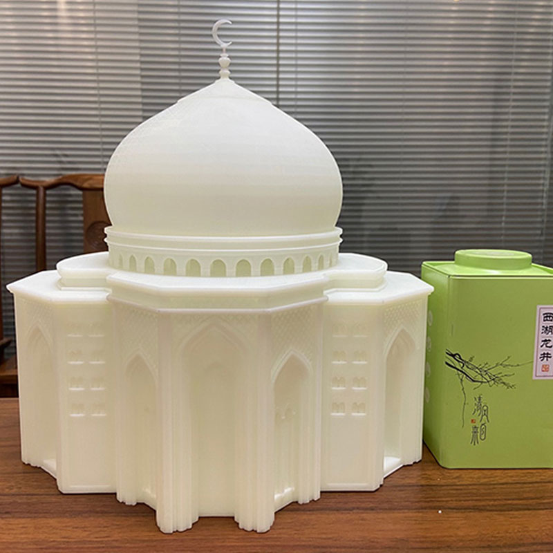
Shoe Molds
- – Measuring Accuracy: 0.01mm
- – Type: Model
- – Scanning Range: 50mm-2000mm
- – Scanning Mode: Photographic Blue Light Scanner
- – Effective pixel: 2-5 Million Pixels
- – Precise 3D Scanning Service Features: Good details, high point cloud density, automatic feature splicing, and automatic turntable
The fabrication of 3D printed products is based on the design files. There are some details and features that always need to be taken into account when designing a 3D printing part, but the best result varies depending on the different 3D printing services.Wonder Tech have a wide range of process and materials to choose from, each with its own benefits and applications.
Specifications
Parameter
Material
I often hear people say that 3D printing and 3D scanning can be applied in the shoe industry, but few people understand how it is applied, so Wonder Tech will take you to understand the application of 3D printing in the shoe industry.Let’s take a look at the traditional shoe mold making process.
- Upload drawings
- 2D engineering drawing
- 3D CAD
- 3D CAM
- NC wood molded copper pole
- Wooden mold, copper pole decoration
- Wooden mold. Copper pole confirmation
- Silicone
- plaster model
- Foundry
- planer
- Imitation bed, milling machine
- Discharge (EDM)
- Sculpture
- Clamping
- welding
- modify
- First model
- Revise
- tryout
- Cooperate with modification
- tryout
- Cooperate with modification
- Bite
- plating. Teflon
Do you feel that the steps are very cumbersome and complicated? So how can 3D scanning technology be applied in the traditional process shown in the figure above?
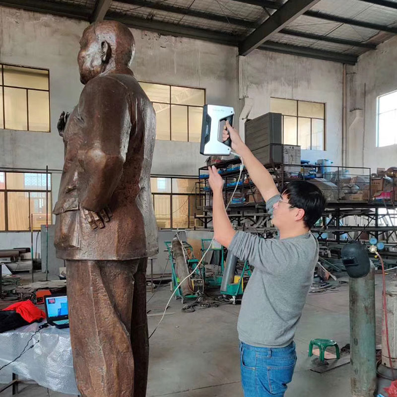
Sample Data Acquisition
At present, most shoe mold customers provide samples, and then hand over to shoe mold manufacturers to make shoe molds according to the samples provided. The processing of the shoe model is inseparable from its 3D data. If you use a 3D scanner, you can directly obtain high-detail data of the sample, and then draw 3D data that can be used for CNC machining.
The 3D sole data was created using Rhino software.
Disadvantages:
- There are errors in manual measurement, resulting in 3D data distortion;
- It is difficult to measure complex surfaces;
- Manual measurement is less efficient.
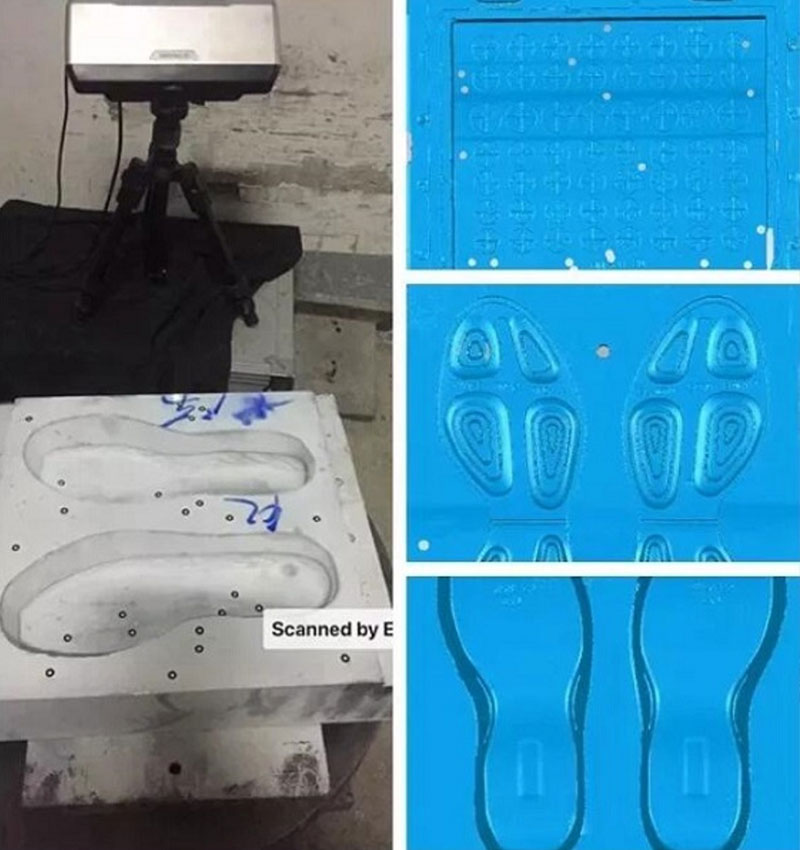
Utilize 3D scanning technology
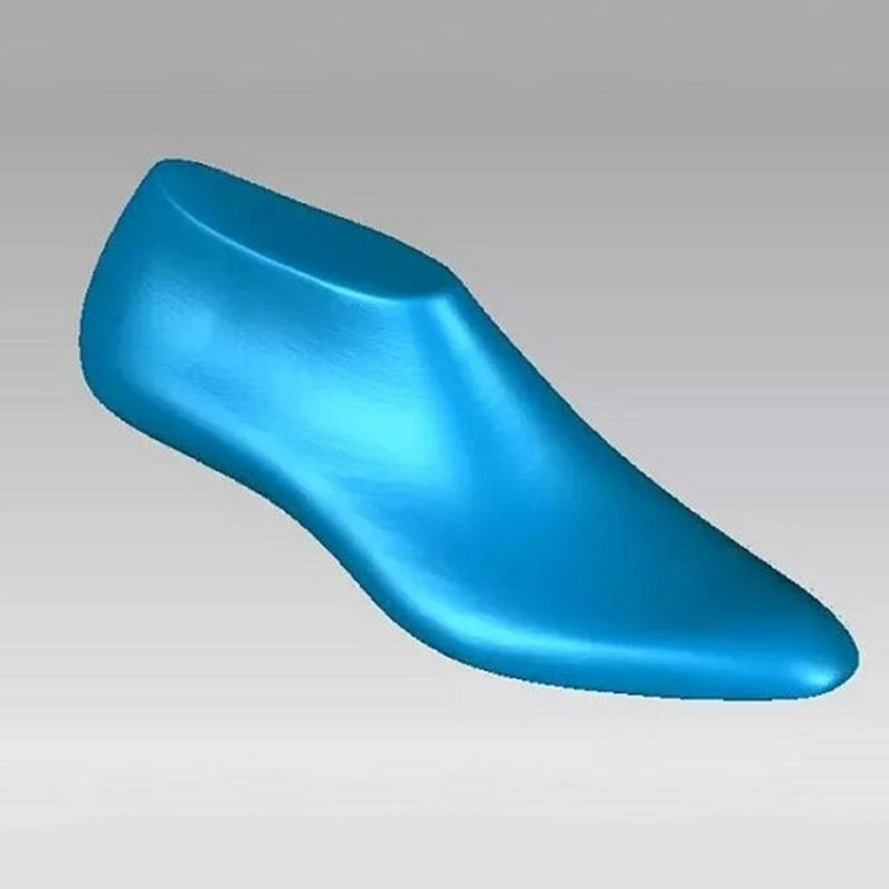
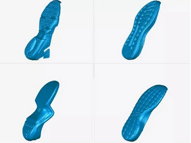
For the sole model samples with complex shapes and many curved surfaces, use a 3D scanner to obtain sample data with a higher degree of restoration.
Step 1: Use the turntable scanning mode of the EinScan-SP desktop 3D scanner to scan fully automatically, complete the scanning of the sole sample in eight minutes, automatically splice the data, and generate closed STL data with one click.
Traditional Sample Data Acquisition Methods
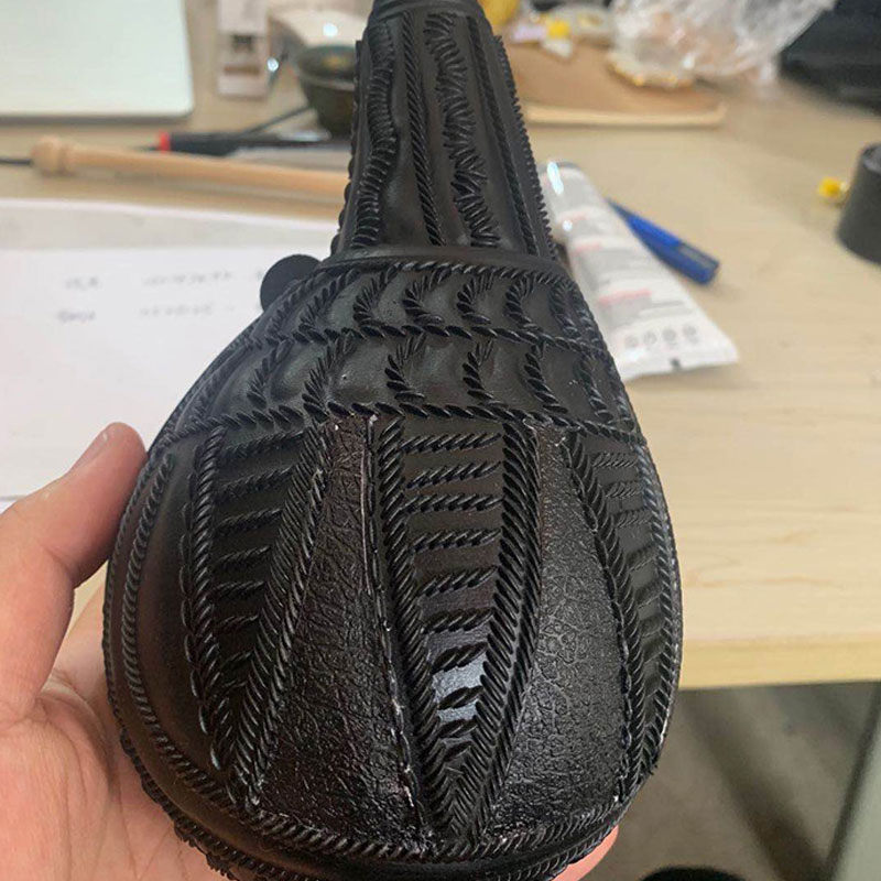
According to the sample provided by the customer, the 2D drawing master uses traditional measuring tools to measure the key positions of the sample.
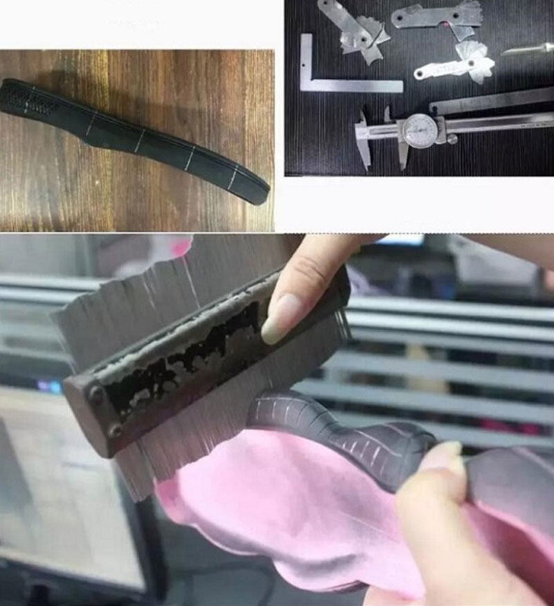
Use the measurement tool to “clip out” the key clamp position (the position of the white line on the upper left shoe sole sample), so as to obtain detailed data on the clamp position.
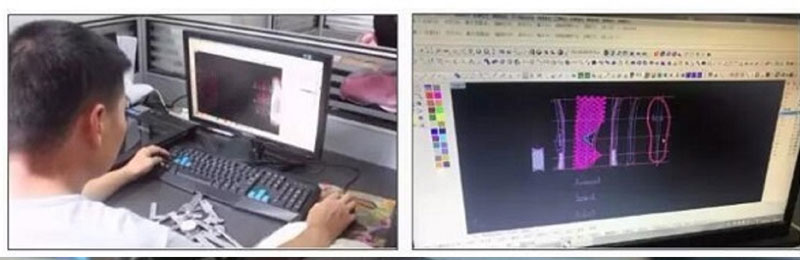
According to the measurement data, combined with the actual shape of the model, the 2D drawing master uses Rhino software to unfold the measured data in two-dimensional form in the software.
The 3D Sole Data Was Created Using Rhino Software
According to the measurement data, combined with the actual shape of the model, the 2D drawing master uses Rhino software to unfold the measured data in two-dimensional form in the software.
The 3D sole data was created using Rhino software.
Disadvantages:
- There are errors in manual measurement, resulting in 3D data distortion;
- It is difficult to measure complex surfaces;
- Manual measurement is less efficient.
Utilize 3D scanning technology
For the sole model samples with complex shapes and many curved surfaces, use a 3D scanner to obtain sample data with a higher degree of restoration.
Step 1: Use the turntable scanning mode of the EinScan-SP desktop 3D scanner to scan fully automatically, complete the scanning of the sole sample in eight minutes, automatically splice the data, and generate closed STL data with one click.
Step 2: Import the acquired data into Rhino software to create 3D data
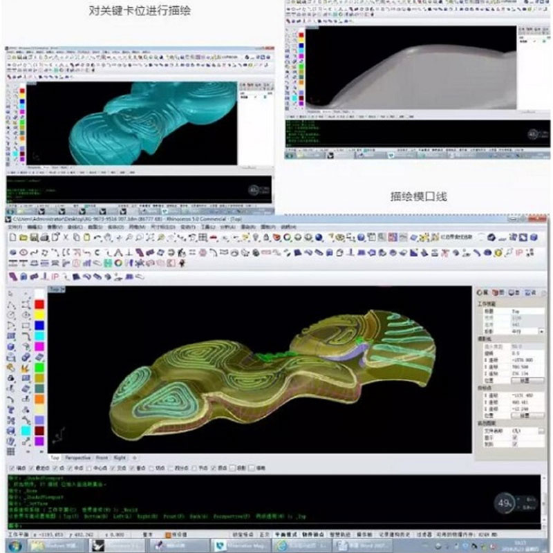
Create finished 3D data in the software for post-processing.The Advantage follow:
- No need for drawing personnel;
- Direct drawing based on 3D scanning data, more intuitive and efficient;
- Samples with complex shapes and rich surfaces can be drawn accurately and conveniently;
- It can be directly measured on the scanned data with small error.
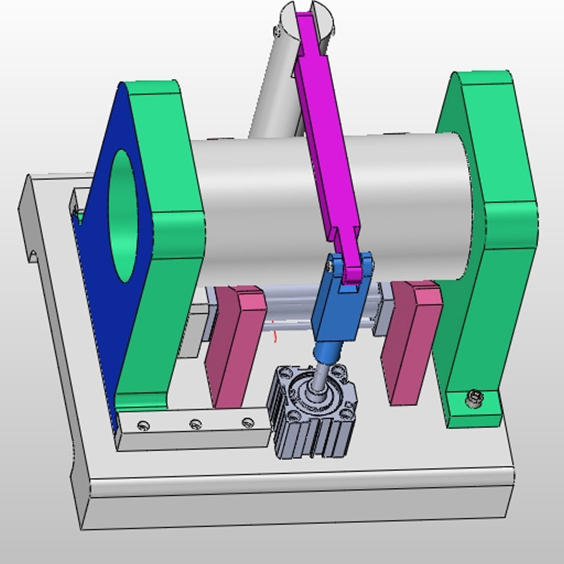
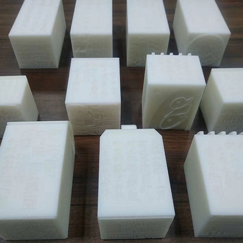
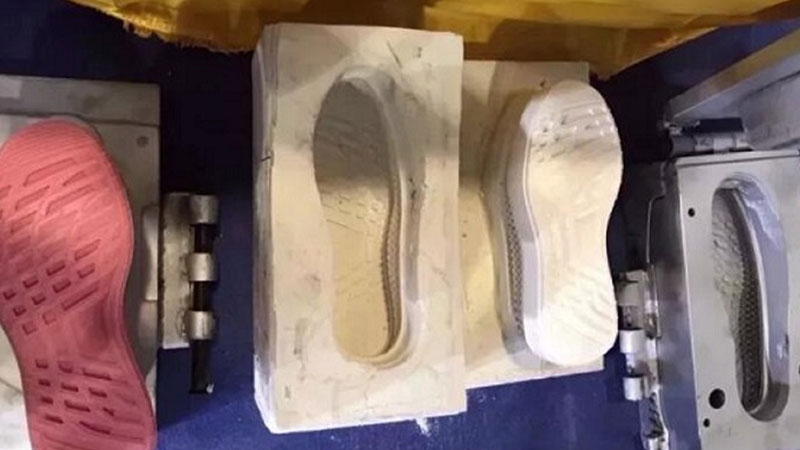
3D Scanning Shoe Mold Casting
Due to the complex pattern and many free-form surfaces, the lower mold of the shoe mold is difficult and expensive to process by CNC. Therefore, most shoe mold factories produce shoe molds in the form of “CNC processing of the upper mold and sand casting of the lower mold”.
For the lower mold model of shoe sole manufactured by sand casting, the sand foundry mold will be more or less deformed, which leads to the inconsistency between the mold and the original 3D data, and the upper mold of the shoe mold is processed by CNC using 3D data, which will also lead to the sand foundry lower mold The die opening line of the CNC upper die is not aligned, and the color separation groove and the parting surface cannot be properly matched.
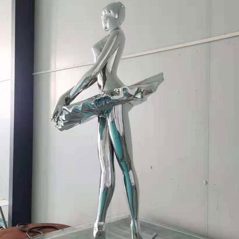
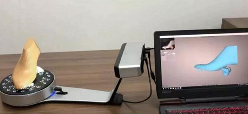
3D Scanning Shoe Model
Traditional shoe last plate-making can only be mastered by skilled old technicians; in addition, the traditional way is to test last, try on shoes, and manually modify the shoe last after the shoe last is completed. Due to manual errors, it often needs to be repeated several times, which is time-consuming and laborious.
Use 3D scanning technology to scan shoe lasts for shoe last redesign and shoe last error analysis; it can also be used to extract die line and establish sole model data suitable for this shoe last.
World-Class 3D Scanning Shoe Molds Services
According to the measurement data, combined with the actual shape of the model, the 2D drawing master uses Rhino software to unfold the measured data in two-dimensional form in the software.
Wonder Tech is dedicated to providing game-changing solutions- high-performance solutions and faster 3D Scanning Shoe Molds services with flexible designs.
We have brought nearly 20 years of materials and manufacturing expertise to every layer of your 3D products to help you in unlocking every dimension of 3D printing techniques.
If you need to make or 3D model design and modeling shoe sole molds, you can contact [email protected], we provide one-stop printing design and modeling services.
3D Printing Technology And Material Table
At present, the commonly used 3D printing technologies include Multi Jet Fusion(MJF), Selected Laser Sintering(SLS), Stereolithography(SLA), Fused Deposition Modeling (FDM), and Direct metal laser sintering (DMLS).
| Cumulative Technology | Basic Material |
| Fused Deposition Modeling (FDM) | Thermoplastics, eutectic system metals, edible materials |
| Electronic Beam Freeform Fabrication (EBF) | Almost any alloy |
| Direct Metal Laser Sintering (DMLS) | Almost any alloy |
| Electron Beam Melting (EBM) | Titanium alloy |
| Selective Laser Melting (SLM) | Titanium alloy, cobalt chromium alloy, stainless steel, aluminum |
| Selective Heat Sintering (SHS) | Thermoplastic powder |
| Selective Laser Sintering (SLS) | Thermoplastic, metal powder, ceramic powder |
| Polypropylene (PP) | plaster |
| Laminated Object Manufacturing (LOM) | Paper, metal film, plastic film |
| Stereolithography (SLA) | Light hardening resin |
| Digital Light Processing (DLP) | Light hardening resin |
Our Quality Promise
Have an idea? have a napkin sketch? From proof of concept to functional tools for the manufacturing floor, 3-di.com has multiple 3D printing technologies at our disposal to help you bring your design to life. Contact us today!Send your files to reiceve a quote. Accepted file types: Hi-Res .stl, .sldprt. .step, .jpg, .pdfInspection reports included with every orderAccuracy up to 0.01mm, maximum size 1500mm100% visual inspection for every part Highly vetted 3D printing partnersMaterial certifications availableQuality guaranteed. If your parts aren’t made to spec, we’ll make it right.Over 100 machines running 24 hours a dayMore than 60 experienced masters
3D Printing Part Sizes
| FDM | 200 x 200 x 200 mm for desktop printers, up to 900 x 600 x 900 mm for industrial printers |
| SLA | 145 x 145 x 175 mm for desktop printers, up to 1500 x 750 x 500 mm for industrial printers |
| SLS | 300 x 300 x 300 mm, up to 750 x 550 x 550 mm |
| DMLS/SLM | 250 x 150 x 150 mm, up to 500 x 280 x 360 mm |
| MJF | 380 x 285 x 380 mm |
Dimensional Accuracy In 3D Printing
The dimensional accuracy refers to how accurate the size and form of the printed part are compared to that in the CAD design. Factors that affect dimensional accuracy include material quality, equipment, post-processing, and more. Dimensional tolerance, shrinkage, and support requirements are three key elements to measuring dimensional accuracy. Below are the dimensional tolerance of different 3D processes.
| FDM dimensional tolerance | prototyping (desktop):±0.5% (lower limit:±0.5 mm), industrial:±0.15% (lower limit:±0.2 mm) |
| SLA dimensional tolerance | prototyping (desktop):±0.5% (lower limit:±0.10 mm) industrial:±0.15% (lower limit:±0.01 mm) |
| SLS/MJF dimensional tolerance | ±0.3% (lower limit:±0.3 mm) |
Layer Height In 3D Printing
Layer height is a measurement of the amount of material extruded by the printer’s nozzle for each layer of your part. It is measured in microns or millimeters. The selection of layer height is important for some 3D printing technologies, such as SLA and FDM. Below are the typically applied layer height for different processes.
- – FDM: 50 – 400 μm
- – SLA: 25 – 100 μm
- – SLS: 80 – 120 μm
- – MJF: 80 μm
- – DMLS/SLM: 30 – 50 μm
3D printing and prototyping have advanced development in recent years. With these improvements, metal 3D printing has become a possibility. Metal 3D printing is used in a variety of sectors. Companies that use metal 3D printing are discovering that 3D printing complicated metal parts in low quantities is considerably more cost-effective than traditional methods of production. Metal 3D printed items are cheaper and have a wider range of material alternatives. Aluminum is a popular metal for 3D printing since it is both sturdy and lightweight. Steel is another extensively used material that is perfect for industrial applications due to its strength, good polish, and temperature tolerance. Metal 3D printing is utilized in a wide range of sectors for a variety of purposes. Functional prototypes, end-use parts, Jigs, tooling, and fixtures are some of the applications.
| Metals | Applications |
|---|---|
| Stainless steel | Utensils, cookware, and other items that could ultimately come into contact with water |
| Bronze | Vases and other fixtures |
| Gold | Rings, earrings, bracelets, and necklaces |
| Nickel | Coins |
| Aluminum | Thin metal products |
| Titanium | Strong, solid fixtures |
3D Printing Plastic Materials Guide
Wonder Tech provides plastic 3D printing services with constantly high efficiency and quick turnaround. Advanced 3D printers and optimal materials allow us to ensure both cheap prices and premium quality.
| Plastics | Features | Applications |
|---|---|---|
| ABS | Tough, strong, durable, heat-resistant, cost-effective, flexible, reusable, not biodegradable | Car bodies, appliances, and mobile phone cases |
| PLA | Easy to work with, environmentally friendly, biodegradable, available in resin and filament with a variety of colors | Food packaging, biodegradable medical devices and implants |
| PVA | Water-soluble | Often use to create a support structure for portions of a product that may warp or collapse |
| PP | Affordable, chemical resistant, flammable, and degrades with UV light | Household containers, lab equipment, and textiles |
| Nylon/PA | Strong, lightweight, durable, heat and impact-resistant, but not resistant to strong acids and bases | Applications that require high mechanical properties and functional prototypes |
| PEI | Can withstand high heat | Injection mold tools and heat-resistant components |
| PC | Heat resistant up to 135 °C, durable, impact and shatter resistant, moderately flexible, transparent, electrically non-conductive | Prototype windows and other clear products |
| PMMA/Acrylic | Good impact strength, comparable clarity, and UV absorption properties | Automobile headlights, commercial aquariums and other alternatives to glass |
| CPVC | High heat distortion temperature, chemical inertness, dielectric, and flame and smoke properties | Chemical processing, power generation, semiconductor, wastewater treatment |
| PEEK | Wear-resistant, good weight-to-strength ratio, high thermomechanical properties | Medical custom-made implants, devices, aerospace and automotive parts |
| PETG | High impact resistance, excellent chemical and moisture resistance | Compliant mechanisms, water bottles, electronic enclosures |
| TPU | Flexible, abrasion-resistant, resistant to impacts and many chemicals | Sporting goods, aerospace and automotive |
| PETP/Ertalyte | High dimensional stability, mechanical strength, low moisture absorption, physiologically inert | Thin films, containers for liquid drinks |